Acorn/BBC Master 128 - CMOS Battery Pack and Computer Configuration
This document provides essential information for those wishing to: (1) replace the CMOS Battery packand/or (2) restore Master 128 Configuration settings. |
(1) The Master 128 battery pack.Warning: All the information in this section is provided on the basis of my own proven techniques. However I take no responsibility for any damage caused through faulty workmanship or by not taking sensible precautions to ensure that correct polarity of operation is maintained under all working conditions.The batteries used for this pack assembly should be 'Duracell' class Alkaline AA batteries only. NOT RECHARGEABLE batteries. This is the reason for the resistor and diode sub-assembly present, i.e. to inhibit the battery recharging intended for the Lithium cells which were first fitted as a part of the Master 128 design. Thus, it must be ensured that the diode is fully functional and installed with the correct polarity. The general arrangement diagram, below, shows the layout and details the specifications of the semiconductors which should be used.
|
|
| It could be useful to utilise the plug, lead and semiconductor assembly of the old battery pack. If the battery pack has leaked electrolyte then take care when handling as the effusion is corrosive and presents a hazard for skin and eyes and should not be ingested. Note: When preparing ends for soldering (points W,X,Y and Z) it is more effective to allow sufficient length for curling the ends into loops or spirals, somewhat larger in the case of points X and Z at the negative battery ends. This will ensure a stronger joint, more quickly made with less build up of heat in the battery. Cut the 0V line close to the negative end of the lower left battery (point Z in diagram) and re-prepare the end for soldering later - strip, clean, loop and tin. The diode (D1) is usually attached by a short length of wire, the wire having been soldered to the battery first (high heat) and then to the diode (less heat), this to prevent overheating and destruction of the diode. Thus it is best to separate the diode from the wire, rather than the wire from the battery. This should be a quick operation with a soldering iron, preventing heat damage to the diode. In order to keep the two batteries, between points Z and Y, in line and ensure permanent contact between them it is useful to construct a tight fitting tube from about 160g/m2 card or fire-retardant material if preferred, by wrapping tightly around batteries and securing with tape. The tape I find useful here is that white masking tape commonly used when paint spraying. For connecting points XY and point W to D1, short lengths of copper wire, single strand about 22 or 23 SWG (0.025 inch or 0.65mm), should be prepared with looped and tinned ends as mentioned previously. Pre-tin all battery ends. Solder wires at WXY and Z. Then solder wire attached at W to D1. Arrange the flying leads and tape these and the WX battery to the tube containing the Z-Y batteries, conforming to the general arrangement in the diagram. Before locating assembly into the space at left of the keyboard ensure that the two batteries (Z-Y) are making firm contact, a tight fitting tube will help to ensure this, and check output at PL8 using a multimeter. An alternative method.If all the above seems a bit 'hairy' then another solution would be to adapt a 4x AA battery holder of the type commonly available from Maplin, fitting the flying leads, plug and semi-conductors in a manner that maintains polarity as in the diagram above. This could be located in the space between the main PCB and the PSU.This arrangement would certainly simplify replacing batteries at a later date, albeit at the increased risk of inserting batteries with polarity incorrect. Consider that another party may obtain the computer after you and may not be aware of the polarity issues. If this method is adopted it would be a good idea to clearly and permanently identify the + and - ends of the holder's individual cell locations. |
Which has been done! |
| Chris Walker has emailed me with pictures and a brief description of his method using a 4xAA cell holder (Maplin order code CL19V) and a dummy battery to contain the resistor and diode assembly. The dummy AA battery is available from Maplin, having order code YX92A in the catalogue I have here (1999-2000), priced at about 64p ex VAT. |
| WARNING: Ensure that correct polarity is maintained at all times throughout the construction. The diagram at the start of this section may be used for reference. |
|
|
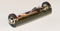
Above: The Maplin dummy AA battery with the internal terminal connecting metal strap removed and the diode and resistor assembly soldered in. WARNING: Ensure that the polarity of diode/resistor assembly conforms with the expected polarity of dummy cell. |

|
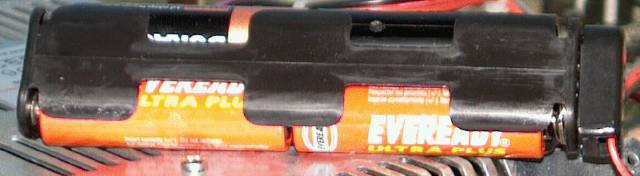
| Above: Dummy battery, complete with resistor and diode assembly, fitted into Maplin holder with other standard AA alkaline batteries. Chris suggested that it was probably a good idea to rotate the dummy battery such that the resistor and diode are hidden from view or touch. |
|
| Above: The completed battery assembly. |
(2) Master 128 Configuration.Note: _fc indicates the flashing cursor, Bold type indicates key presses or commands. Computer only writes to screen are inmonospacedtype.
First carry out a factory reset which in the case of the Master 128 is switching on with the R key held down (unlike the RISC OS 'DELETE'), the screen will look like: CMOS RAM reset Press BREAK and you get a loud beep and on screen:
Hold down CTRL and D and press BREAK, you get another beep and on screen, where _fc is flashing cursor: Acorn MOS Acorn 1770 DFS This is not a language *_fcIf you don't get this at this stage then something other than flat batteries is the cause. at the *prompt enter ROMS and you should see something like this: ROM F TERMINAL 01 ROM E VIEW 04 ROM D Acorn ADFS 50 ROM C BASIC 04 ROM B Edit 01 ROM A ViewSheet 02 ROM 9 DFS 79 ROM 8 ? ROM 7 ? ROM 6 ? ROM 5 ? ROM 4 ? ROM 3 ? ROM 2 ? ROM 1 ? ROM 0 ? Now at the *prompt enter ST. (for STATUS) and you should get this: Configuration status: Baud 1 No Boot Shift Caps Data 0 Delay 0 Directory Internal Tube FDrive 0 File 0 Hard Ignore 0 Lang 0 Mode 0 No Tube Quite Print 0 Repeat 0 Scroll TV 0,0 *_fc Now at the *prompt enter the following, case not important but spaces after CO. are: CO. BAUD 4 CO. NOBOOT CO. CAPS CO. DATA 4 CO. DELAY 50 CO. NOTUBE CO. NODIR CO. FDRIVE 0 CO. FILE 9 CO. FLOPPY CO. IGNORE 10 CO. LANG 12 CO. MODE 135 CO. LOUD CO. PRINT 1 CO. REPEAT 5 CO. SCROLL CO. TV 0,1Now do a CTRL/BREAK If you find that the floppy drive hunts (other than when accessing track 0) then try alternative CO. FDRIVE 3 as some drives prefer this (very rarely now a 1 or 2 will work). If you wish to UNPLUG or INSERT ROMS (all those listed above are in the one MegaRom) then enter *UNPLUG x or *INSERT x where x is the decimal equivalent of the hex number of the ROM displayed in the list after *ROMS. The DFS at ROM 9 is in the MegaRom and was bugged. Many masters had an updated DFS inserted into one of the spare ROM sockets at ROM 8. In this case issue a *UNPLUG 9 and *CO. File 8 followed by a CTRL/Break. The Delay and Repeat (for key reading), Mode and Loud/Quite (beep) settings are a matter of taste. If after the computer has been switched off (for at least 15 minutes maybe more) you find it as bad as before then replace the battery pack and repeat the above. |
Feel free to e-mail me with any comments and feedback.